This project started because I always wanted to do something with the ‘octal’ tubes I had lying around. As a kid I already played with ECC’s, ECL’s etc, but never with these type of tubes. So what is simpler than a 0V2 receiver to cover AM and/or CW? The receiver works fine, it is quite sensitive when it is tuned and operated (regenerate!) correctly. Apart from the high end of the AM and the 160 and 80m amateur bands, the broadcast stations around 3 and 3.9 MHz are loud and clear, and also some fax and/or weather stations. I have not yet connect the output to my PC (running for instance MIXW) to decode these. Also, DRM (Digital Radio) is appearing as loud noise. Can’t do anything with this I suppose.
The schematic diagram is straightforward.
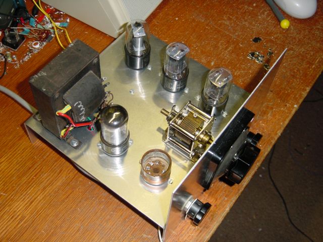
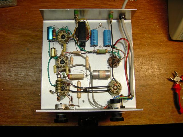
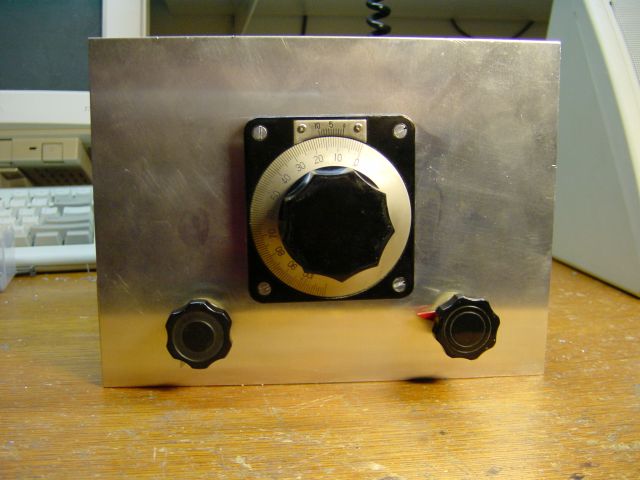
Top view. The coil, 40 wnd’s on a 6V6-base is in the middle bottom, left to the capacitor. Behind the coil the 6X5 rectifier, in front of the transformer giving 4V, 6.3V and 2x250V (thanks Arie, PA0EZ). The 4V winding is not used. At the other side the 2 6SN7’s (front and middle) and the 6K6 (or 6V6 if you want) output penthode giving lots of noise. The coil covers 1.5 .. 4.8 Mhz. The chassis consists of aluminium 1.5mm, 20×30 cm with 2 sides of 5 cm bend, resulting in 20×20 cm. The front is also 20×20 cm, with the main dial in the middle, the volume-control to the left of it and the generating control to the right.