Introduction
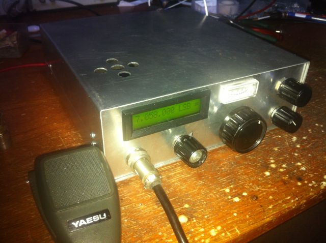
During the spring 2013 I decided to build a shortwave transceiver to participate in the vacation round on 40meters. First with 15W only on 40 meters, and with an open dipole on the camping 3 meters above ground I worked a lot of stations in all of Europe. Back from holiday, I stabilized and the design and added missing functionality. In the front, you see LCD, S-meter and volume with on/of switch. Bottom right is the bandswitch and under the S-meter is the mode switch (LSB/USB and CW).
Design
The vco of the transceiver is a DDS built with a AD9850, running on 100MHz. It was published years ago in UKW-Berichte. The output of the DDS is passed through a lowpass filter and amplified by a MAV11 to give 5mW for the rx/tx mixer, an SBL-1.
 The SBL-1 is used for rx and tx, and switching is done with a cmos CD4066. The IF of 9 MHz is amplified by two BFR90’s and demodulated in a Plessey SL1640. For LSB and USB two sideband oscillators are built with BF199. Mode is selected switching on the required oscillator. Since the vco (DDS) is always oscillating above the RF-frequency, this is easy and directly done by the mode-switch on the front.
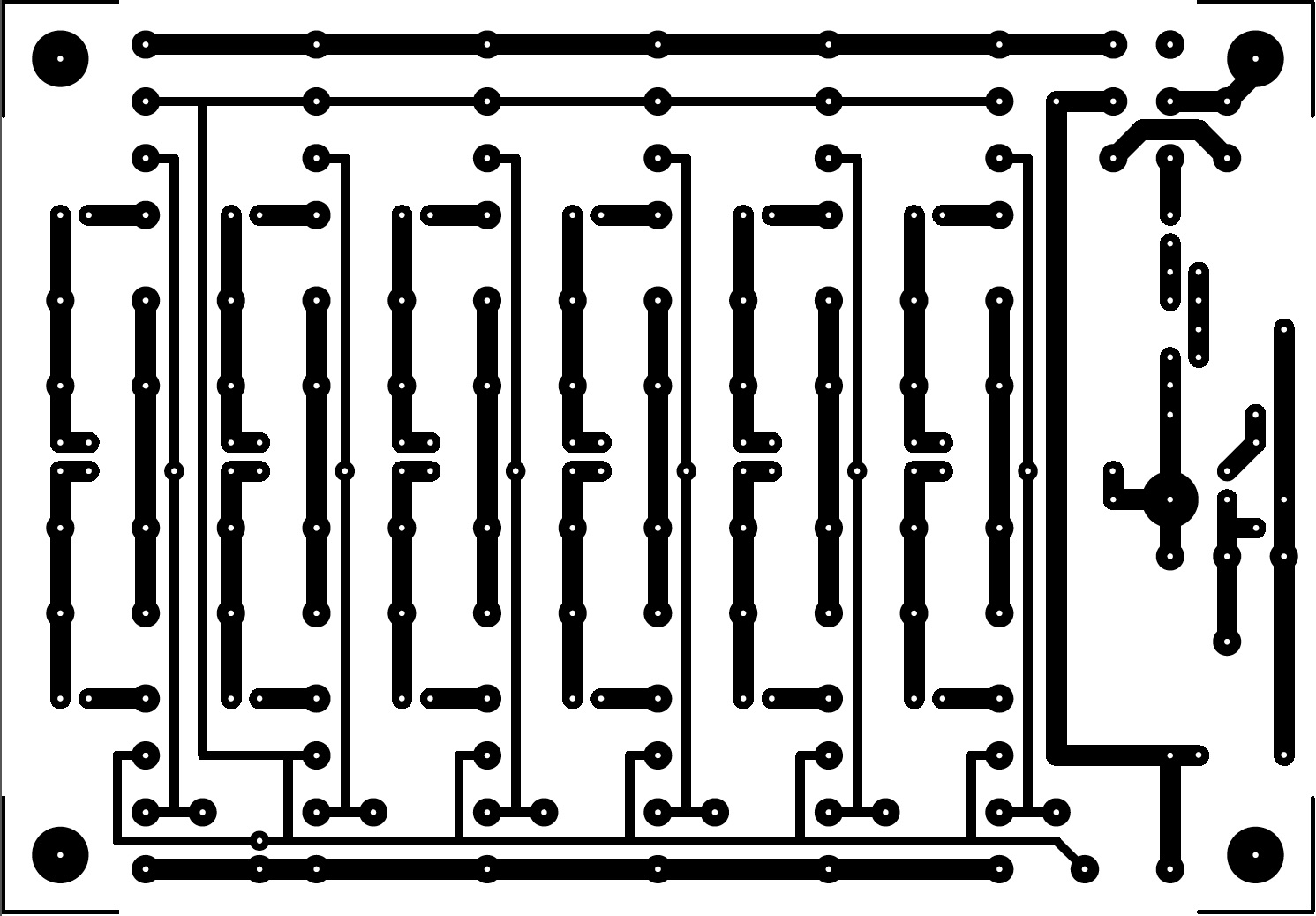
The RF from the SBL-1 is fed to a bandfilter module, made a printed circuit board. The pcb is shown here, and here the component layout is shown. I will update the site shortly with the schematics and a revised component layout where the part values are shown. Six bandfilters with Tchebichef characteristic are built on this board, and the current band is selected by switching a filter on by two small reed-relays. These are 5V types, so that the microcontroller can handle them directly. At the moment only 80, 40, 20 and 10 meter bandfilters are built on the board, so I have room for 2 other band (15 and 30 meters, but also 160 meter could be possible, or even just a lowpass filter to get a general coverage receiver if needed). The filters are built with standard coils (2.5 uH), wound on standard coilformers. The passband attenuation is 6-10dB, this is quite high and mainly depends on the losses in these coils. Some further improvements could be useful here.
The IF-strip was published in Electron, the magazine of the Dutch radio amateurs society in the 90’s.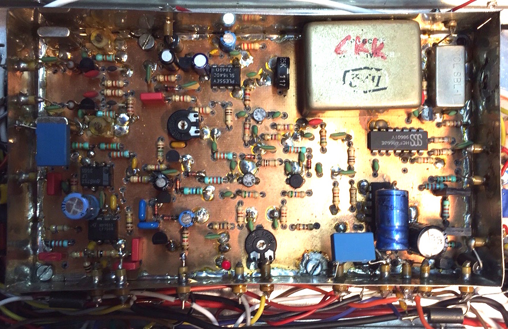
The mixer is an SBL-1, and the IF side of it is switched via CD4066 CMOS-switches for TX or RX. The crystal filter is a XF9B, and the IF amplifier is build with two BFR90’s. The productdetector is a SL1640 from Plessey. The audio is amplified in a 741 opamp, and used to generate the AGC and S-meter. The AGC is of the audio type, and regulating the current through two 1N4148 diode’s which each short the base of the BFR90 for HF to ground via a 22nF capacitor.
The mode switch just powers the corresponding sideband crystal oscillator (8.985 and 9.015 MHz). For CW a side tone sine oscillator is added (not shown) which modulates the mixer and produces a sidetone in the speaker.
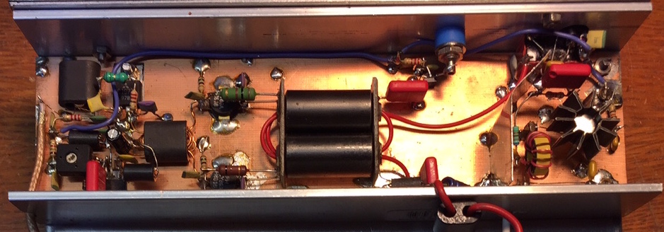
The 35W final amplifier is built with a 2SC1971 driver and 2 BLW31 power transistors. The output transformer is built with 2 ferrite pipes (www.dutchrfshop.nl) with endplates made of 2 pieces of doubleclad pcb, and with pipes made of the shield of RG214 coax. The secundary side consists of 5 turns isolated wire. The bias of the BLW31’s is built around a BD139 as emitor follower. The bias current is adjusted via a potmeter (1k) in series with 1k5 and 2 1N4148’s. These diodes are thermically coupled with (one of the) BLW31. On the right a 20dB preamp is build around a 2N3866 following the design of W7IUV.
The bandpass filter for the amateur bands are switched with small in line relais. A pcb is designed for this.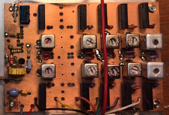
From right to left you see the filters for 80, 40, 30, 20, 15 (still empty) and 10 meters. Switching is done with in line reed relais. When transmitting, the RF signal is amplified 20dB by a BFR96 before feeding it to the power amplifier.
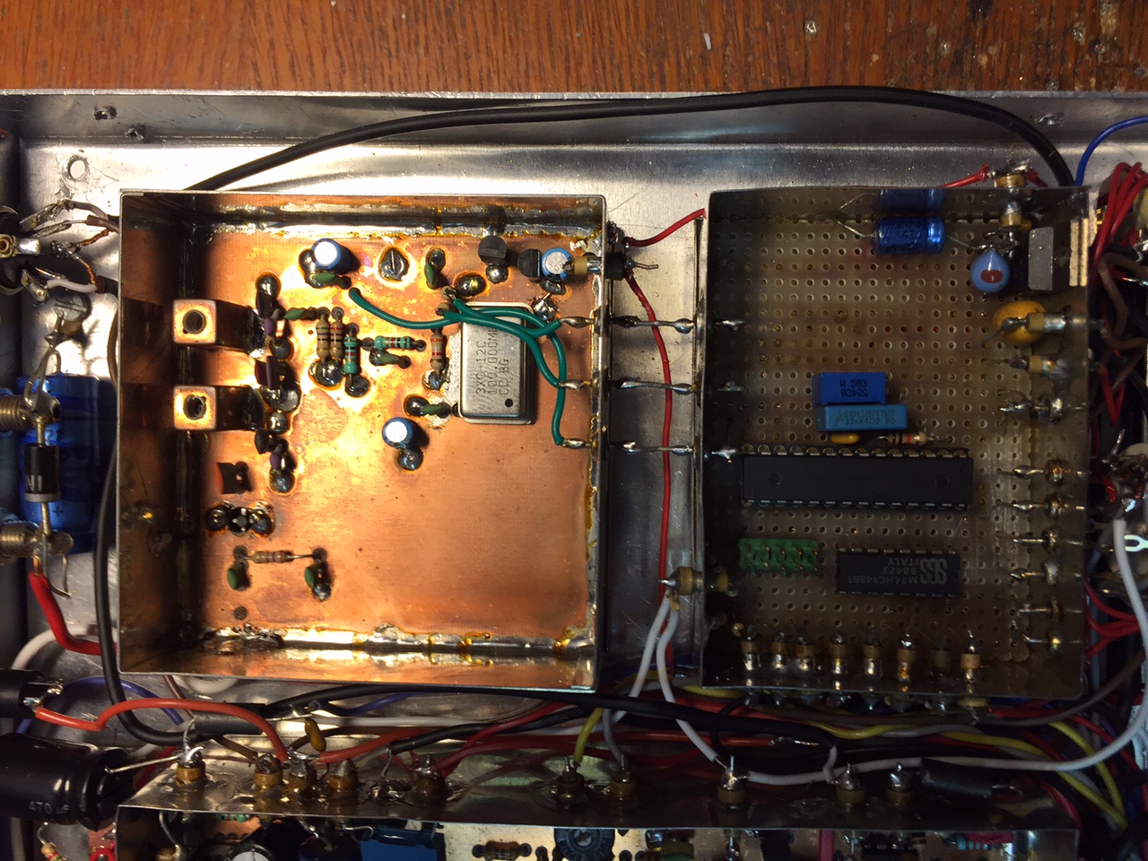
Microcontroller and software
The microcontroller is a single AVR of Atmel, a ATMega8, and a 8-to-3 encoder for the bandswitch. To prevent QRM from this controller it is built in a tin box and all connections are made via feed-through capacitors.
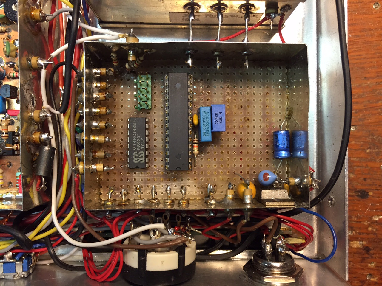 The IO of the AVR is straightforward: 2 pins for the rotary switch, 1 for the pushbutton in this rotary, 6 pins for the LCD (in 4-bits mode D7-D4, E and RS), 3 pins for the band switch, 1 for the mode LSB/USB, 3 for the DDS. (data, clock en frequency update). The microcontroler has its own 7805 regulator.
The software is written in C which makes it easy and powerful. Only the rotary switch is working under interrupt: it increments or decrements a variable which is then read out in the main loop of the program. This way no pules will ever be lost and the rotary follows your tuning smoothly. When the frequency hasn’t changed for 2 seconds, the current frequency is stored in the built-in eeprom in the Atmel. When the transceiver is switched on, or when ons changes the band, the eeprom is read for the current band and the frequency restored. Activating the rotary pushbutton changes the stepsize between 10Hz, 100Hz and 1kHz.
Housing
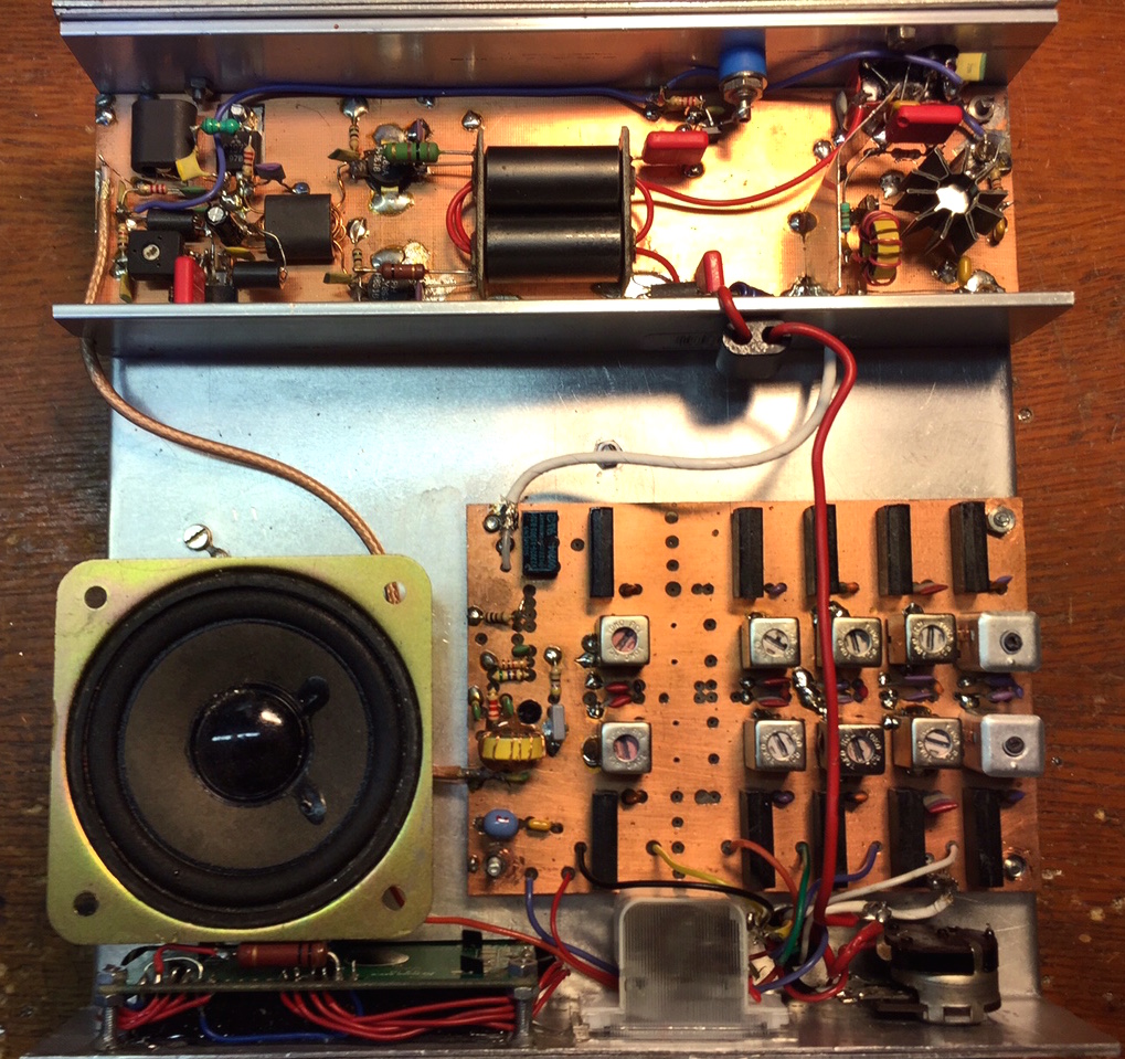
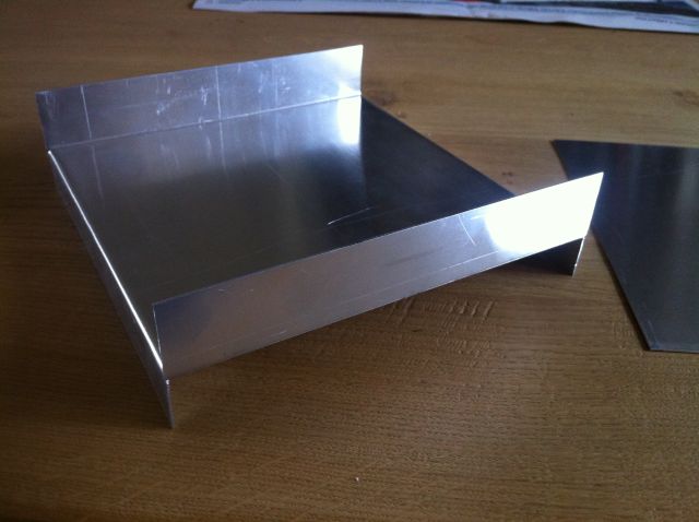
The housing of the trx is made out of 1mm thick aluminum sheet, of which a saddle is build in the vice. The overall size of the case is 20x20cm and 6.5 cm high. A front and back are mounted to the frame with M3 screws and the controls like potmeters and switches. A top and bottom lid complete the housing, giving two compartments for the electronics.
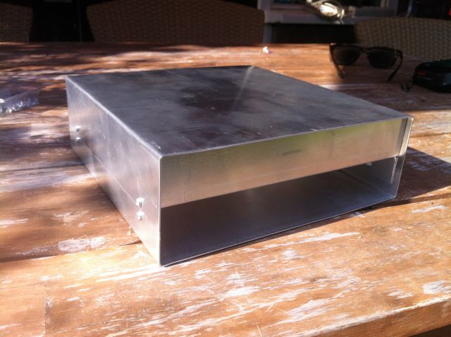
In the top compartment the bandfilters and the power amplifier is mounted, while in the bottom the IF-strip, the DDS and the microcontroller are build. The LCD display I use is higher than 3.2 mm (the height of a compartment) so a hole is needed to give it room.