This transceiver is published in the december 2015 edition of Electron, the monthly magazine of the Veron (in Dutch) and in the july 2017 edition of Funk Amateur (in German).
Please take a look at this page for the modifications to get on the L/v transponder of AO-92 (edit april 2018).
The 23cm band is a beautiful band for all kind of modes, wideband and narrowband: FM-ATV, wideband (stereo) FM, SSB and of course narrowband FM for phone. The 23cm band is very wide so lots of room for experiments: from 1240 to 1300 MHz. Also, quite some repeaters are available, in the Netherlands alone already some 10 repeaters, often located at very high locations of up to 150m above ground.
The only drawback of getting QRV on 23cm is that only a few commercial transceivers are on the market. Often one uses transvertors form 2m to get QRV which work fine for SSB in the SSB-segment (1296-1297MHz), but for repeater usage these are not appropriate because of the large shift. Therefore I decided to design a complete and easy to build FM transceiver.
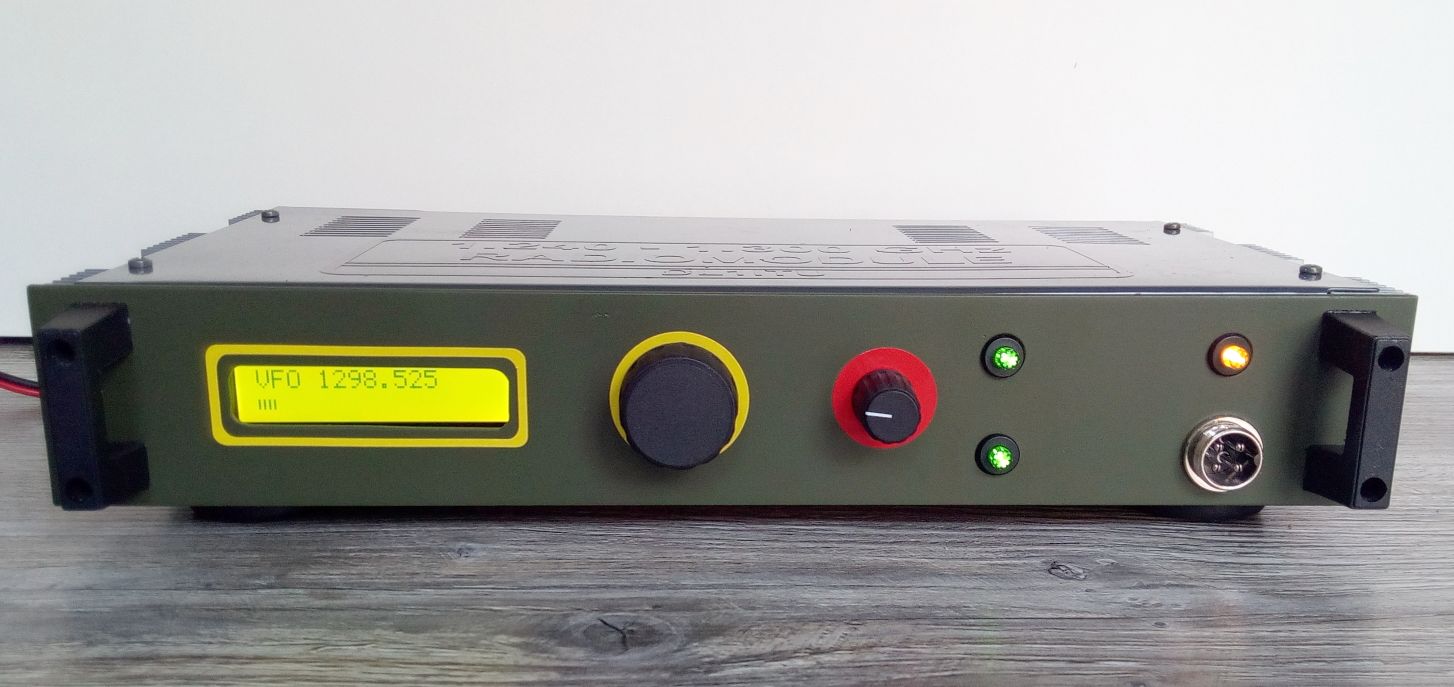
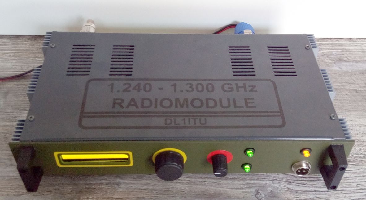
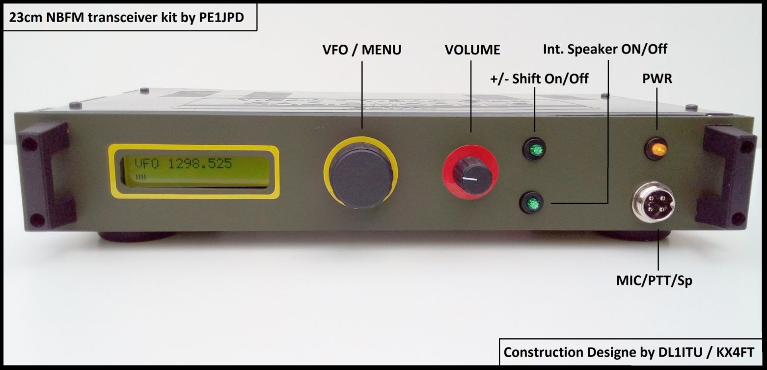
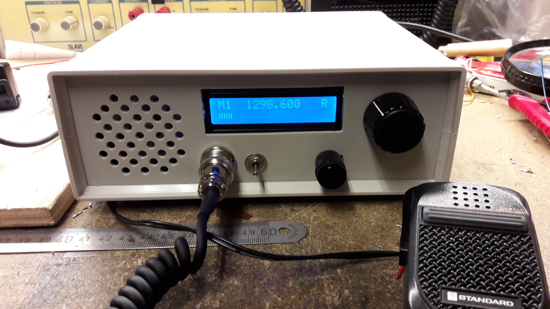
On these pages this 23cm narrow-band FM phone transceiver is introduced. The transceiver is available as a complete kit, including tin shielding box, a professional printed circuit board and all the parts. You only need a housing, a microphone, a speaker and of course an antenna to get QRV on this beautiful band. This is how my prototype looks like:
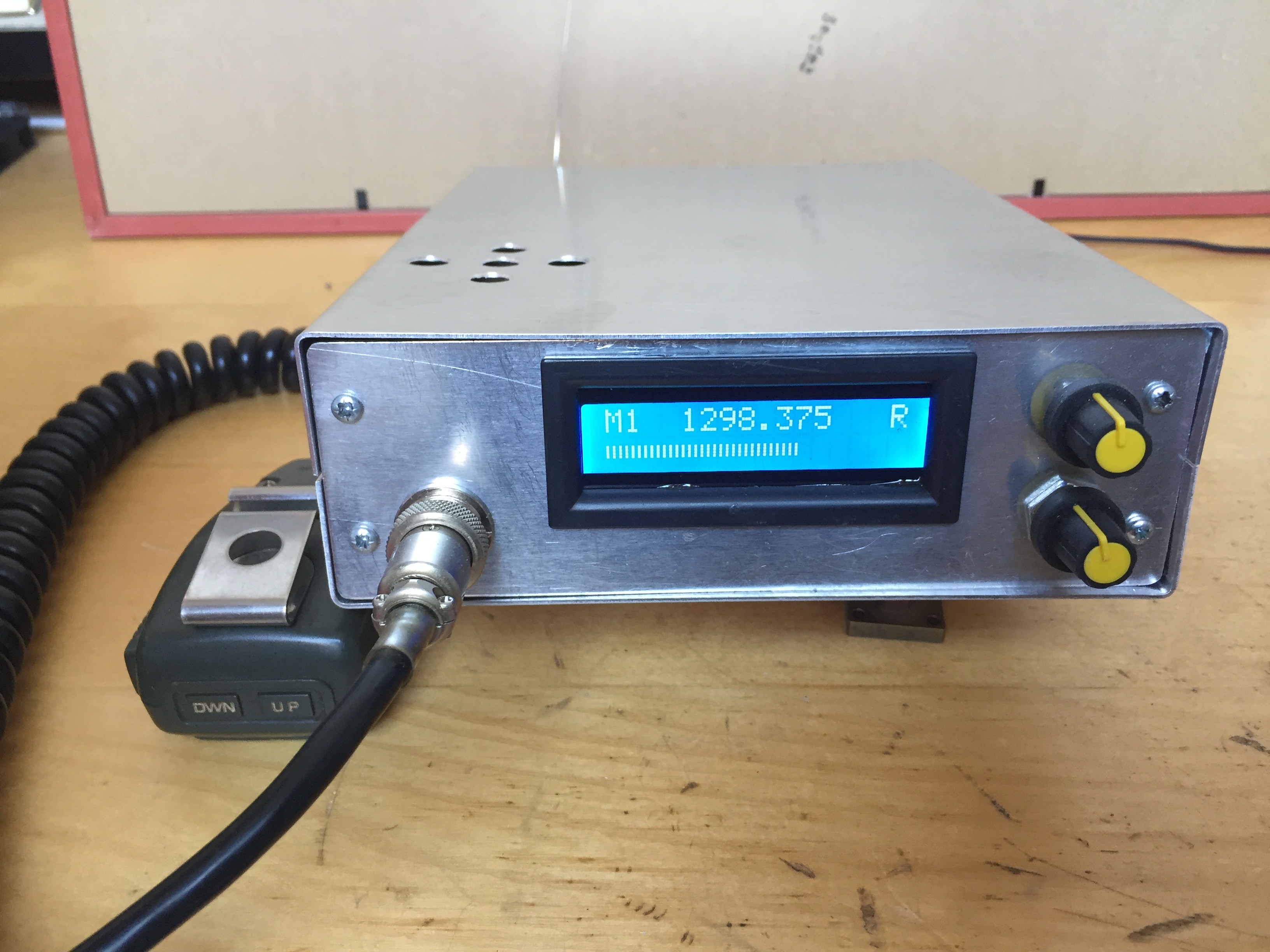 Shown is the operational transceiver while receiving our local repeater PI6NOS at 1298.375 MHz, stored in memory M1. The antenna is just a piece of wire, barely visible. The S-meter is shown in the second line of the LCD.
Features:
- covering the whole band
- for simplex and repeater usage
- output up to 1 watt
- NF 3dB
- LCD with frequency, shift, RX/TX, S-Meter
- VFO and 10 memories, all with own shift and CTCSS
- shift presettable, ie. -28 MHz or +20 MHz, CTCSS 67.5 – 150 Hz
- just connect a microphone, speaker and an antenna to get QRV on 23cm
- Easy to build and expandable, software open-source
Schematic diagram and description
The block diagram of the transceiver is straightforward: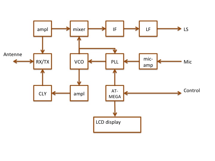
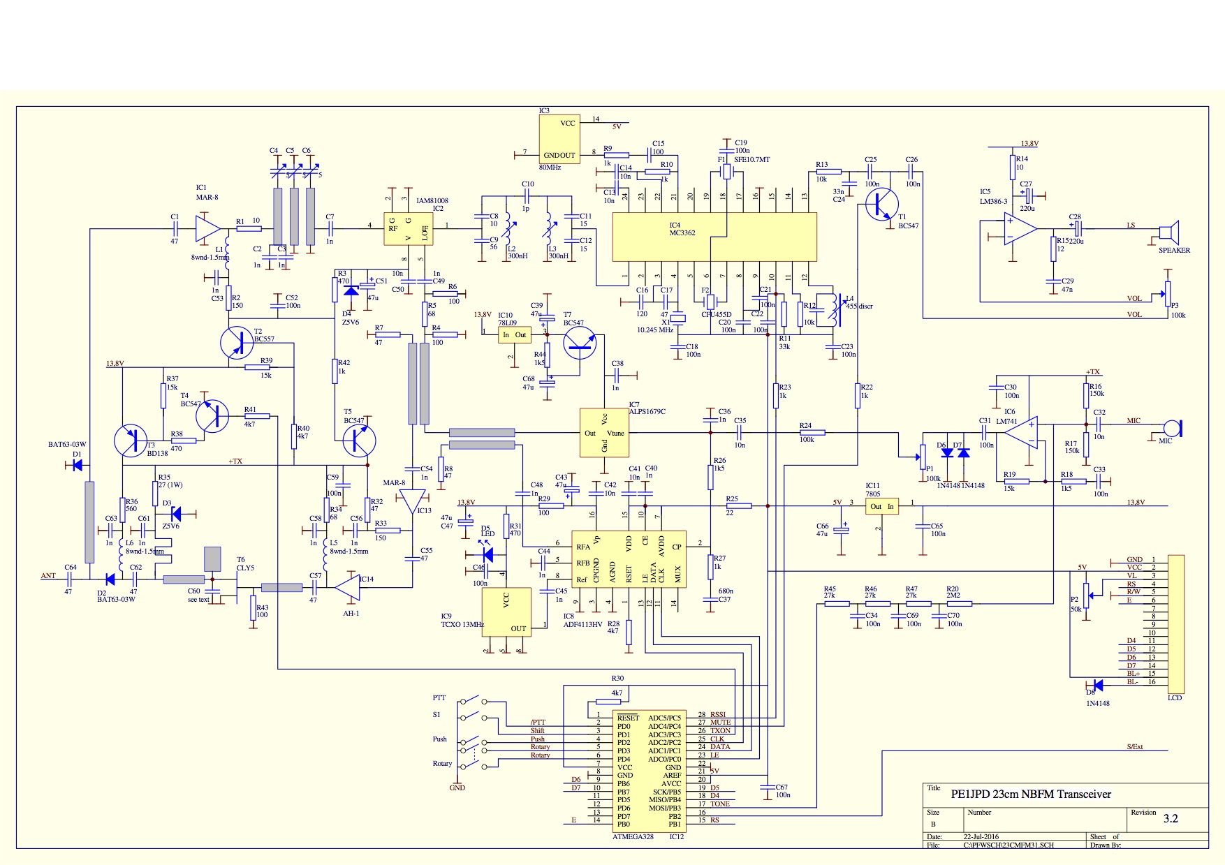
In the final schematic diagram you can recognize the building blocks:
The vco is an ALPS 1679C (IC7) or Y17C which oscillates from 1100 to 1350 MHz. Thesignal is frequency/phase locked in an ADF4113HV (IC8). The HV extension means that it can handle a tuning voltage of up to 16V (normally 5V, so an additional level shifting op-amp would be needed). The output of the vco is 5dBm, which is attenuated 10dB for proper level at the rx-mixer IC2. The modulation is superimposed on the tuning voltage. To get proper modulation care must be taken in the design of the loopfilter around R13, C39, R14 and C36.
The received antenna signal is passed via a rx/tx pin switch to IC1 which amplifies up to 25dB with a noise figure of about 3dB. After a three pole bandpass filter the rx signal is fed to the mixer IC2, an IAM81008 which has a conversion gain of 8.5dB. The first IF is 69.3 MHz, which is fed through a bandpass filter consisting of L1 and L2 and accompanying C’s. The output impedance of the mixer is 50 ohm, and so the filter input is matched to 50 ohm by a capacitive tap. The input impedance of the IF chip is 680 ohm/7pF, so here the tap is done at a higher impedance. The IC chip MC3362 contains a dual conversion FM receiver. The first IF here is 10.7 MHz, which is realized by mixing the 69.3 MHz input with a standard 80MHz (computer) crystal oscillator. The second mixer with 10.245 MHz results in 455 kHz where demodulation takes place. Muting is done via T2 by the microcontroller IC11, which shorts the audio when muted.
When transmitting, the vco oscillates directly on the tx frequency. The output is coupled via a -20dB coupler to IC12 which amplifies 25dB, followed by IC13 (+12dB) and T7 (+8dB) to give up to 1W output. After the PIN-diode antenna switch about 800mW remains.
The microcontroller is an Atmel ATMEGA328, which handles everything in the transceiver. It reads the rotary ecncoder and switches, updates the LCD display, takes care of rx/tx switching, squelch/mute and generating the CTCSS tones. The RSSI signal strength is read from the IF and converted by the internal ADC. As a result the S-meter in the LCD is displayed. The software allows different settings via the menu, stores these in the internal eeprom so it remembers the last frequency when switched off.
The transceiver allows VFO of 10 memory channels, each programmable with their own repeater shift and/or CTCSS. It is possible to continuously scan memories, and the scanning stops for a few seconds when a signal is received. Finally, it is possible to listen at the input of a repeater when a shift is set by closing switch S.
PCB
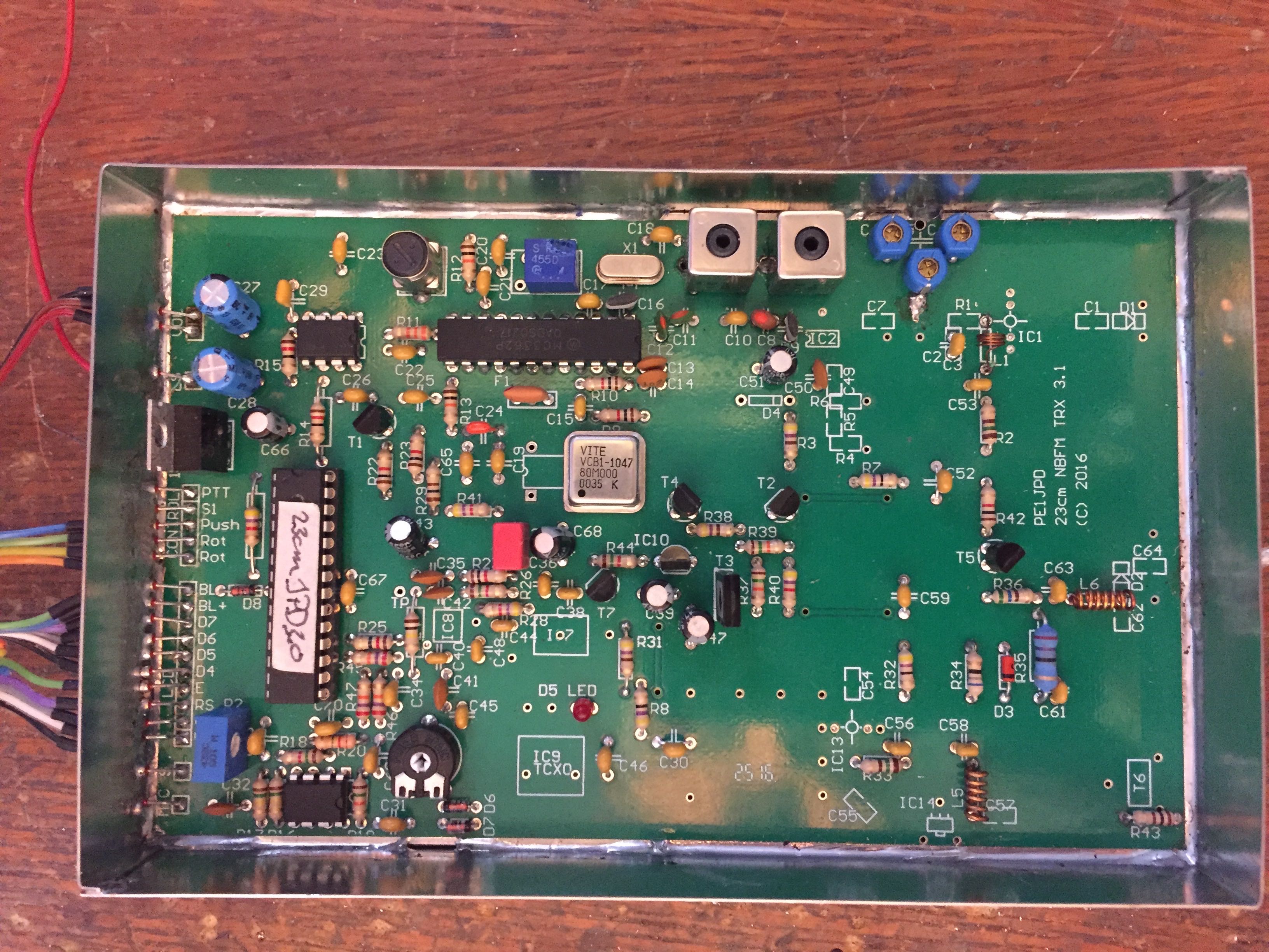
I designed a double sided PCB which is professionally manufactured for this project. On the bottomlayer are the SMD parts mounted (blue), while all “normal” parts are soldered on the toplayer.
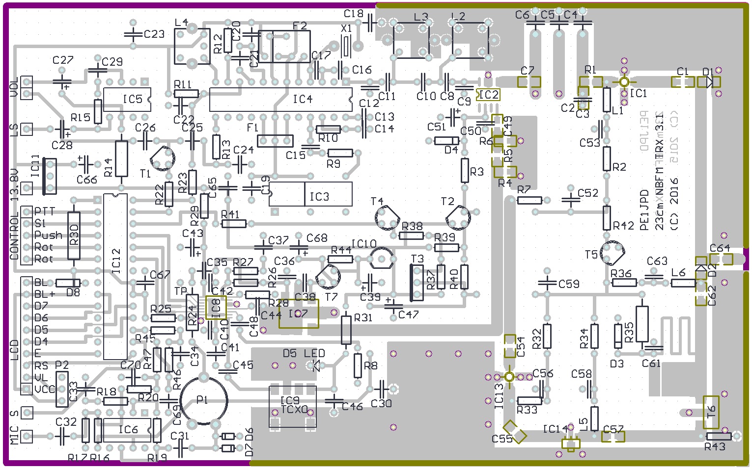 The VCO can be an ALPS 1679C or a Y17C which have a different position of the marking dot. The output-pin (6 resp. 1) connects to the stripline to R4/R5.
User experiences and improvements
The first version of the transceiver is build by about 50 amateurs, and I got nice feedback and also very useful suggestions for improvements. These are all implemented in the latest version from 3.1 and up:
- Software squelch, adjustable via the menu. Two reasons for this change: the IF chip MC3362 doe not support both a good working squelch and a relying S-meter. And the other reason is that the relating circuit in the chip is easily destroyed by shorting the squelch pot to ground. So now the RSSI output of the IF is read into the ADC of the Atmel, and used for muting the audio. Also, the converted RSSI-signal will be translated to a PWM-output on the controller, so that a good working analog S-meter from 0-5V is available for those who prefer this.
- The decoupling of the first 23cm stripline in the filter with C2 is improved by adding an smd C of 1n in parallel to C2.
- The sensitivity of the IF is improved by adding a 1k resistor between pin 21 and 22 of the mc3362.
- C10 and C11 are changed to 27+27p in stead of 27+100pF to match the impedance of the LC filter.
- Audio noise when receiving a strong signal can be reduced by increasing C24 to 33n.
- With an extra small C from drain to source on the CLY5 the output can be increased by 3dB up to 1W. I tune the output with a small piece of copper foil, shifted along the output stripline to find the optimal position.
- to reduce VCO noise the 9V supply is filtered by an additional emitter follower / lowpass.
Measurements
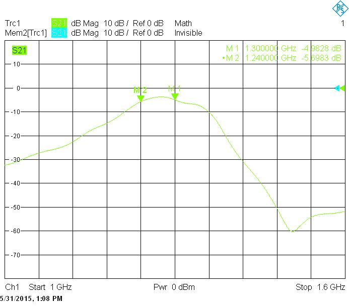
The bandpass filter on 23cm covers nicely the whole band as seen in the plot below. (thanks Ulli from Eisch-Kafka).
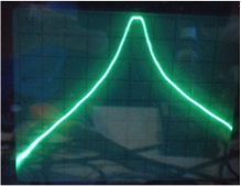
I also wobbled the bandpass filter at the first IF of 69.3 MHz (1 MHz and 10dB/div).
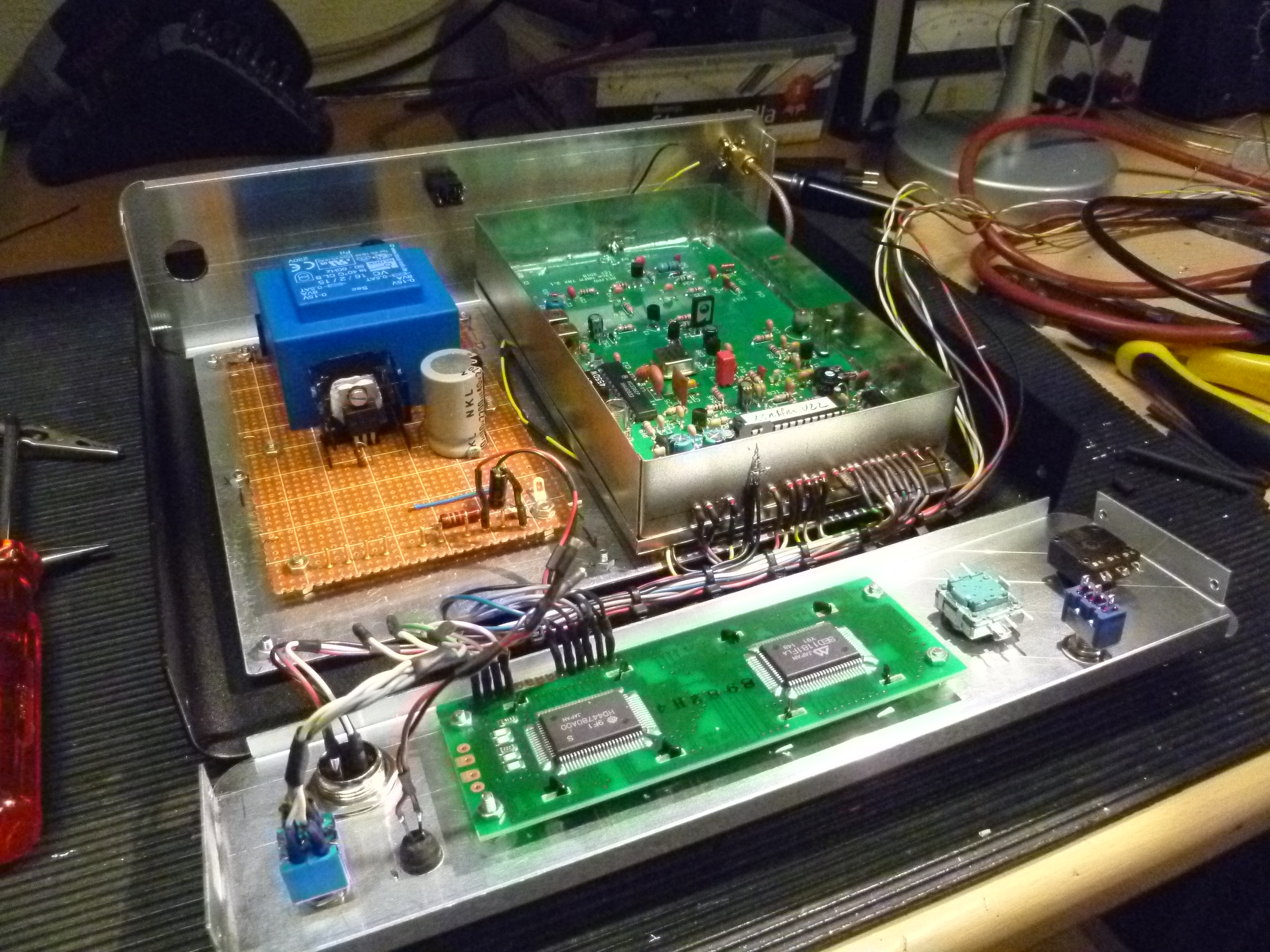
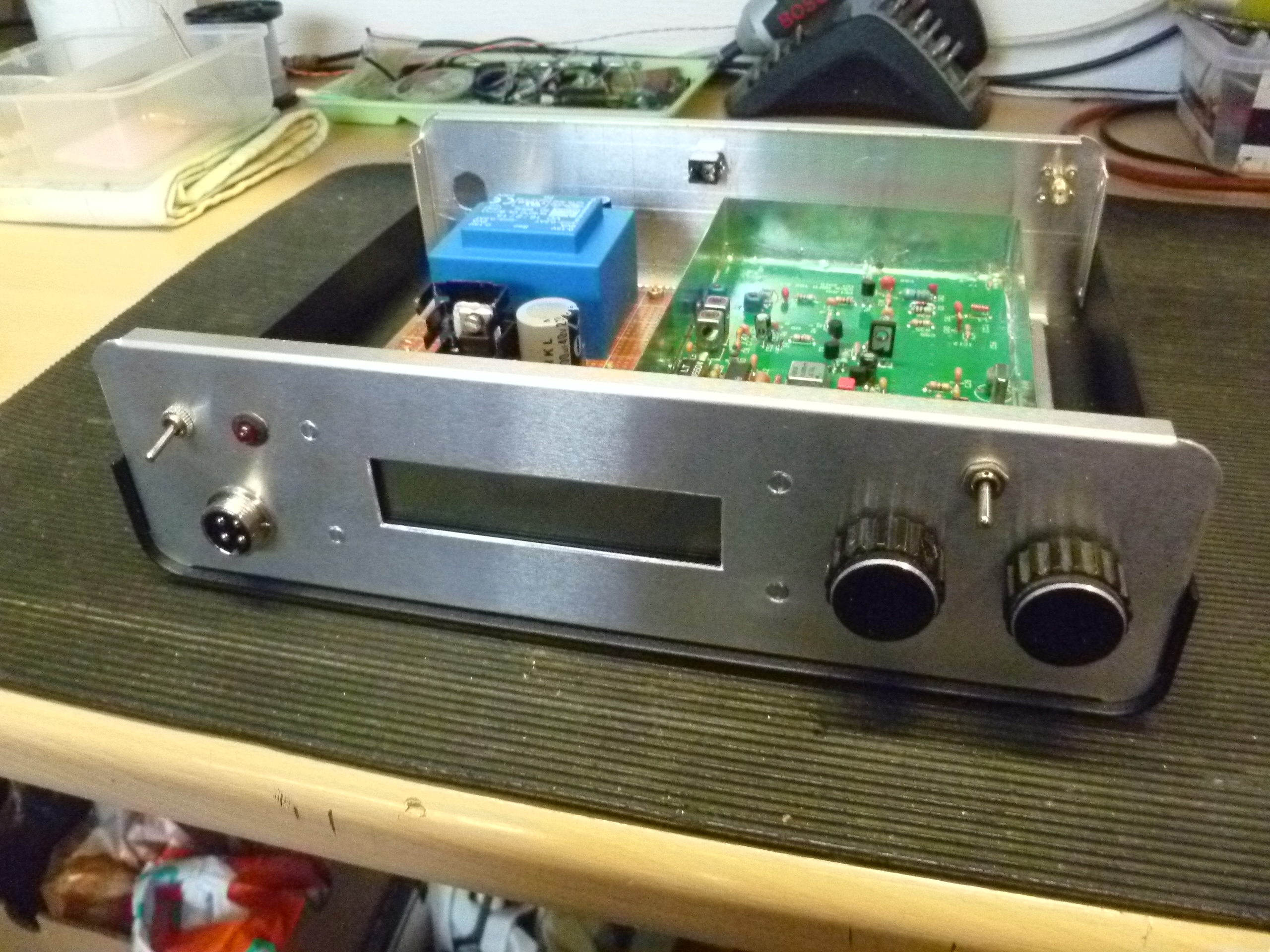
I’ve got a lot of feedback from many amateurs, a few pictures of transceivers build:
 |
 |
| Wil, PA0WBS | |
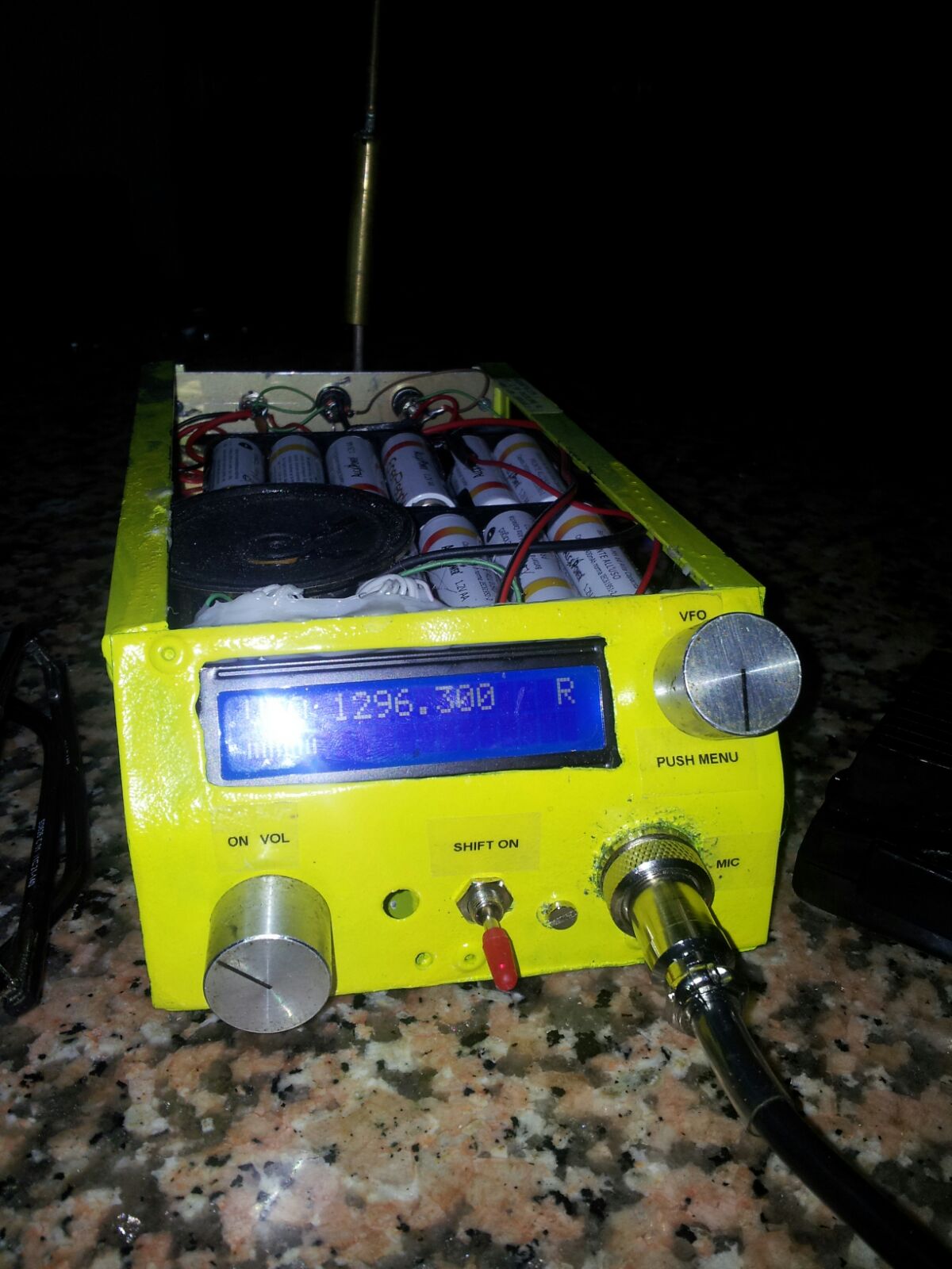 |
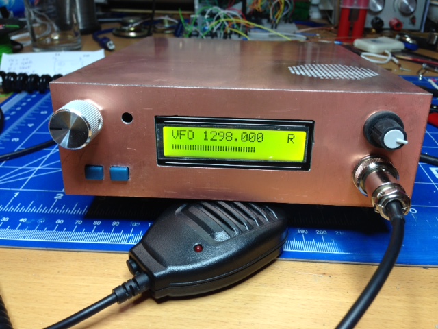 |
| Francesco, IK8PAE | Rolf, PE1PTP |
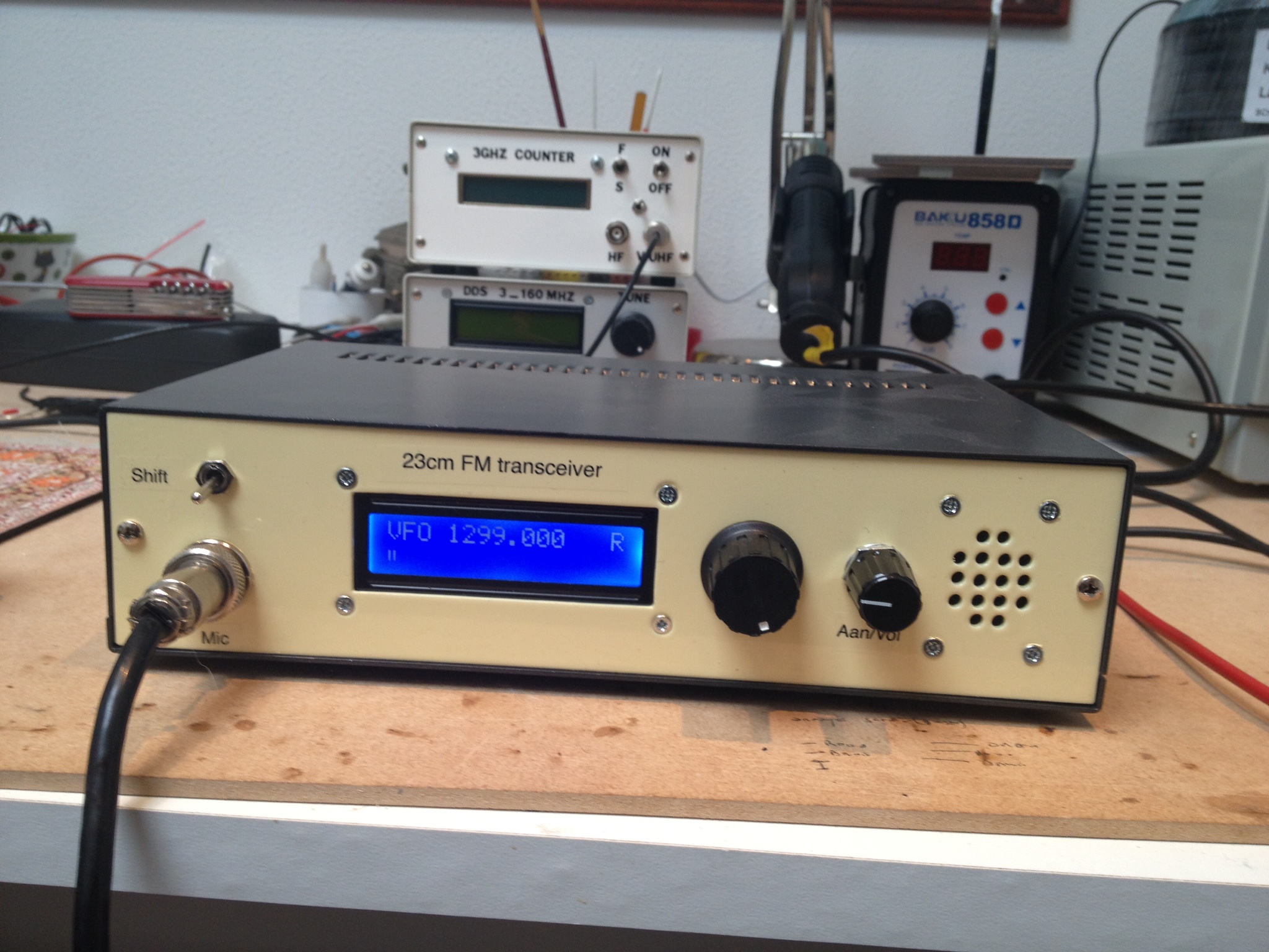 |
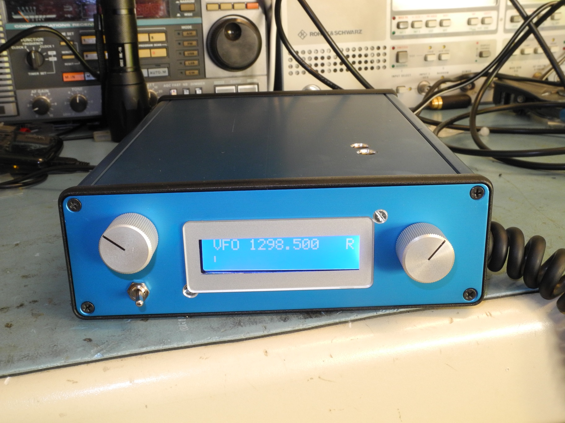 |
| Jan, PA2JS | Erik, PE1RQF |
I love feedback!
Hallo OM Bas!
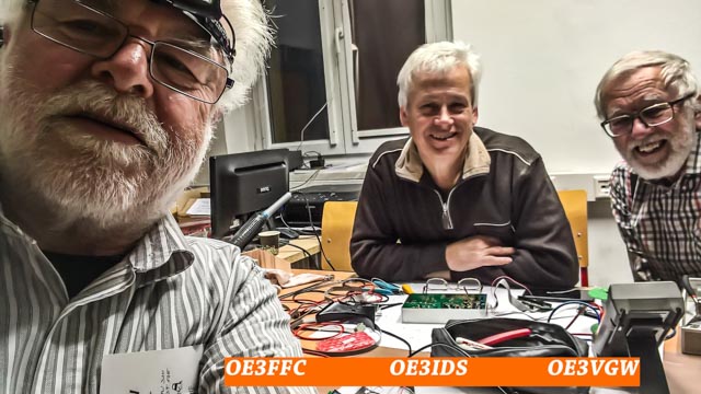
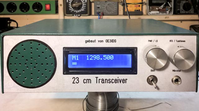
Nun sind wir alle 3 mit dem Bau deines FM TRX fertig geworden und haben
heute unser erstes 2-Weg-QSO gemacht. OE3IDS-OE3FFC.
Anbei ein paar Fotos.
Eine Frage noch, wozu dient der Schalter “Shift”, beziehungsweise wie
verwendet man ihn?
Super TRX jedenfalls und das Bauen hat Spaß gemacht. Vielen Dank für
Dein Projekt.
Vy 73, Franz, OE3FFC
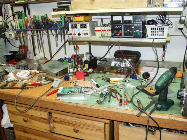 |
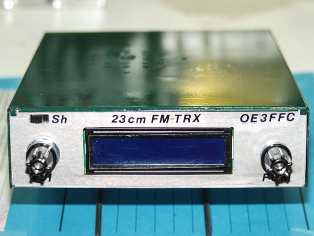 |
 |
 |
 |
 |
Hallo Bas,
vielen Dank für den super Bausatz! Gerät hat auf Anhieb funktioniert. Laute und klare Modulation.
Ein 1750Hz Tongenerator wäre vielleicht noch ein Verbesserungsvorschlag, da es sich bei uns anscheinend noch nicht herumgesprochen hat, daß es CTCSS gibt… hi 😉
vy 73!
Christian, DL1MCG
 |
 |
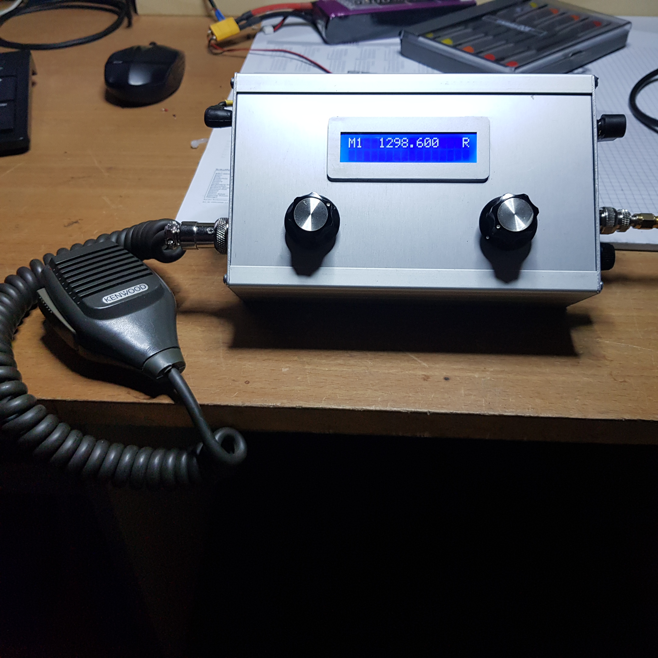
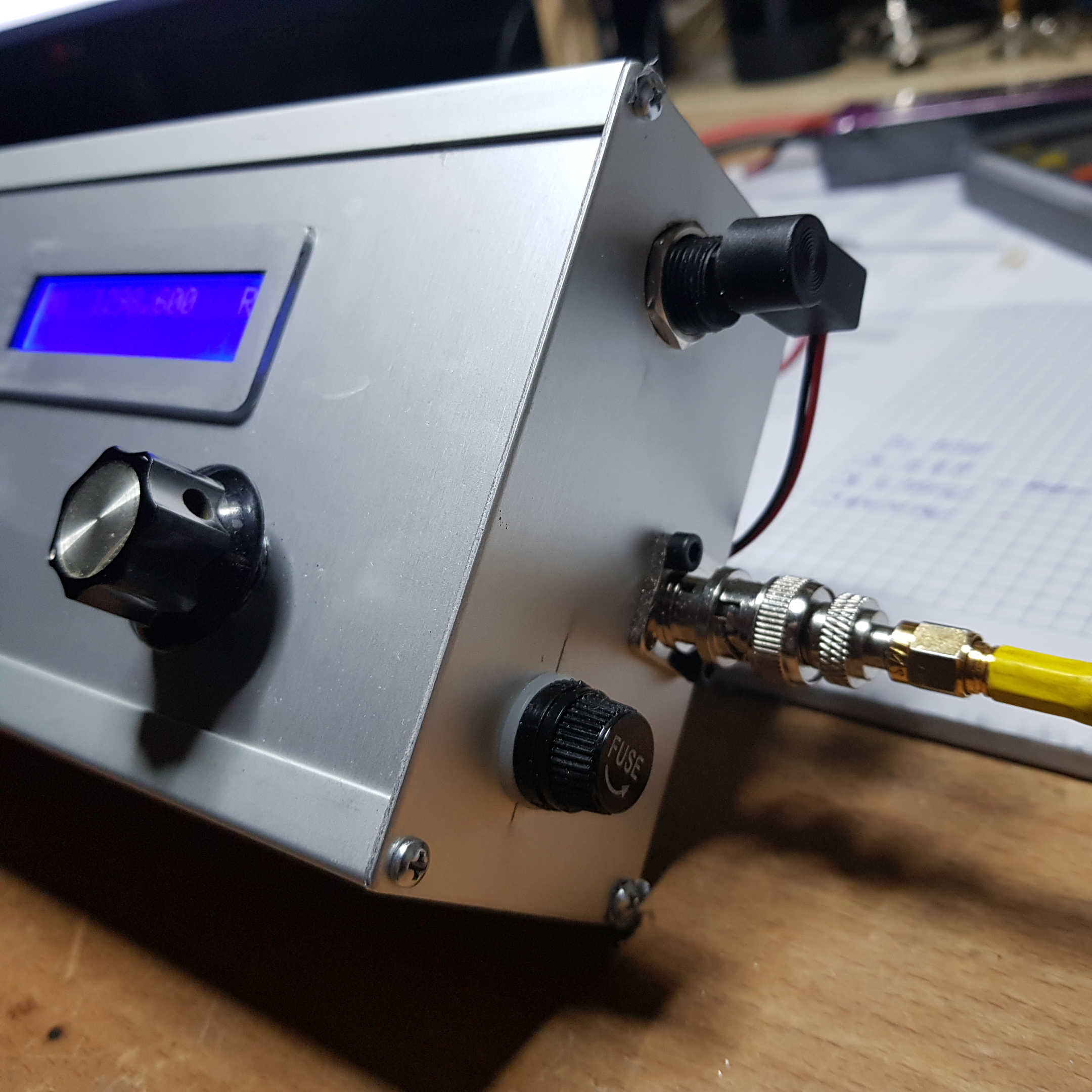
Hello Bas,
We have built 23cm TRX of you, we would like to publish a report about it on our homepage, we are allowed to use the report from the magazine radio amateur, and we will set up a link to your homepage.
The device is doing very well.
Greetings Peter, dl1pn
 |
 |
Hallo Bas,
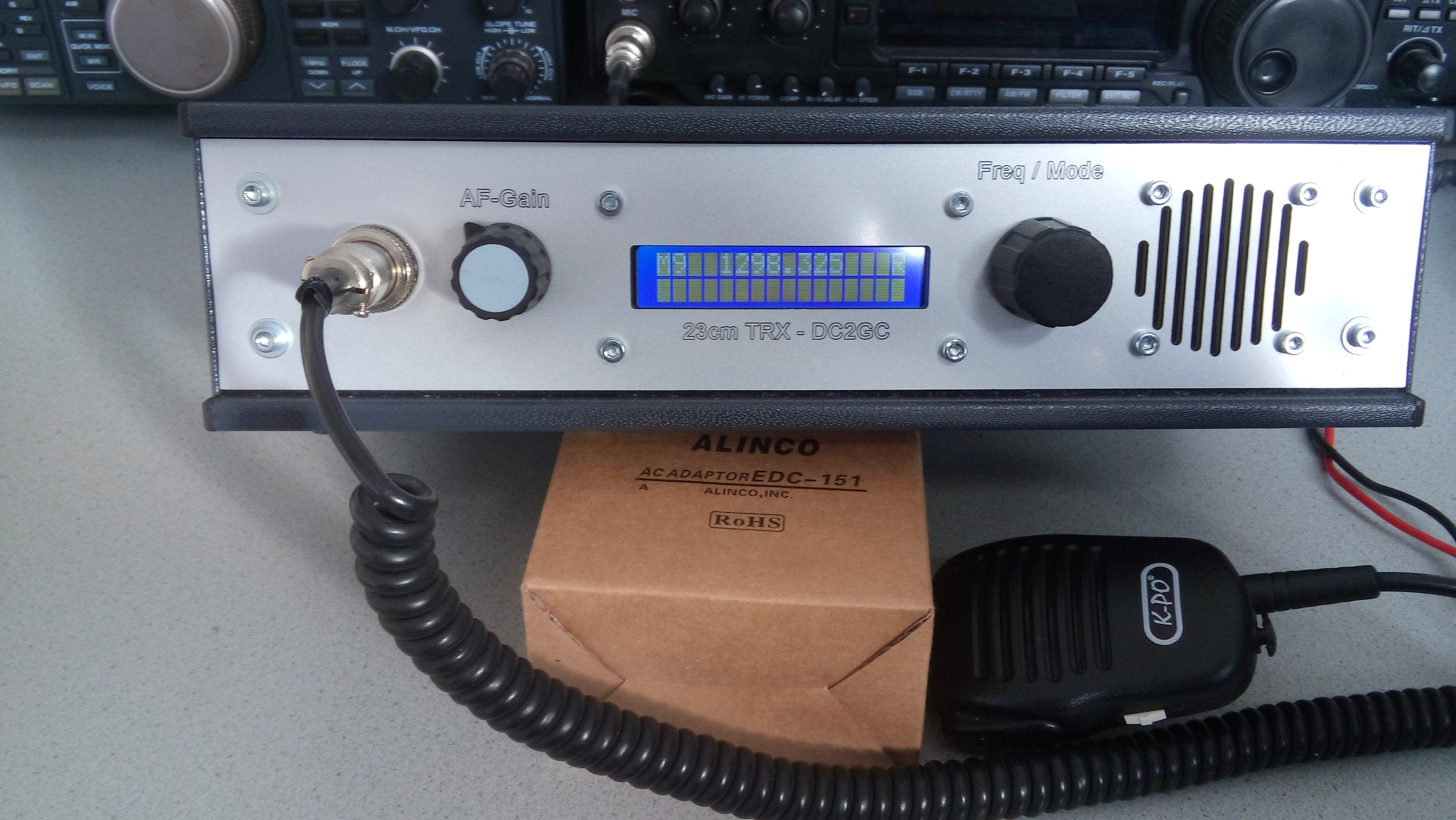
So ich wollte mich nochmal bei dir melden.
Ich habe gestern den 23 cm TRX fertig gemacht und abgeglichen.
Heute hatte ich schon das erte QSO auf unserem lokalen Relais – alles funktioniert ohne Probleme!
Mein weiteres Projekt ist nun das erstellen einer 23cm Entstufe mit etwa 20 Watt.
Herzlichen Dank für das ertellen des tollen Bausatzen – ein gelungenes Gerät.
Dennoch habe ich noch eine Frage. Ist in diesem Bausatz auch ein 1750Hz Ton für das öffnen eines Relais impementiert? – Ich konnte bis jetzt noch nichts finden.
Ansonsten baue ich noch einen Tongenerator und ergänze diesen in dem Funkgerät.
Im Anhang habe ich dir noch ein Bild vom dem Gerät.
Dir und deiner Familie ein schönes Weihnachtsfest und ein guten Start das neue Jahr.
73 Tobias DC2GC
Hoi Bas ,
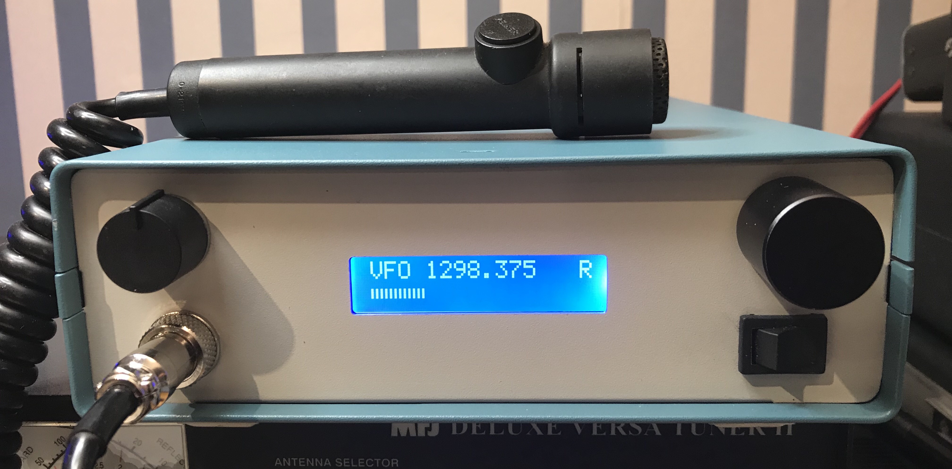
In de bijlage ontvang je een foto van mijn 23 cm set.
Verder is onderstaande link om het DKARS magazine te lezen. http://downloads.dkars.nl/DKARS%20Magazine%20201801.pdf
‘73 de PA7ML
Michel
Hallo Bas,
Danke für den schönen 23cm Bausatz !!
wenn du ein Firmware Update machst, könntest du vielleicht implementieren für ein OLED Display 🙂
OLED Display: https://www.reichelt.de/display-oled-2×16-84x44mm-gelb-ea-w162-xlg-p113320.html?&trstct=pol_5
beste 73
Rüdiger DL1ITU