Update june 20, 2019.
Since the end of January 2018 the satellite AO-92 is operational. This satellite has an FM L/v transponder on board, with an uplink at 1267.350 MHz and downlink at 145.880 MHz. The doppler shift at 23cm is up to 30 kHz up or down.
My 23cm transceiver was originally designed with a step size and fasedetector reference frequency of 25 kHz (phase frequency detector or PFD frequency), so with steps of 25kHz. To correct for the doppler shift a step size of 5 or even 1 kHz is needed. 5kHz is possible with a slightly modified loopfilter and updated software. Drawback of this solution is that the loopfilter gets rather slow and the maximum modulation frequency is limited. However, it works and in february and march I made various L/v QSO’s using these minor changes.
A better solution is to use a ADF4153 fractional N phase lock loop. With these advanced PLL techniques, it is possible to tune in between PFD frequency steps. Now 1 kHz is possible, while the PFD frequency remains high. In fact, the PFD frequency now is 2.6 MHz in stead of originally 25 kHz. So the loop filter is fast and easy. The AD4153 is pin-compatible with the ADF4113, with two differences: Vcc is max 3V3, and Vp (loop voltage) is max 5.5V, and no HV version exists. Luckily, the ALPS vco covers the whole band with a tuning voltage up to 5 or 5.5V. The software is updated to program the different types of PLL, and an extra menu is added to set the tuning step size (1-25-500kHz) to be able to tune fast and smoothly over the band. In short, the following changes are needed on the latest version of the board:
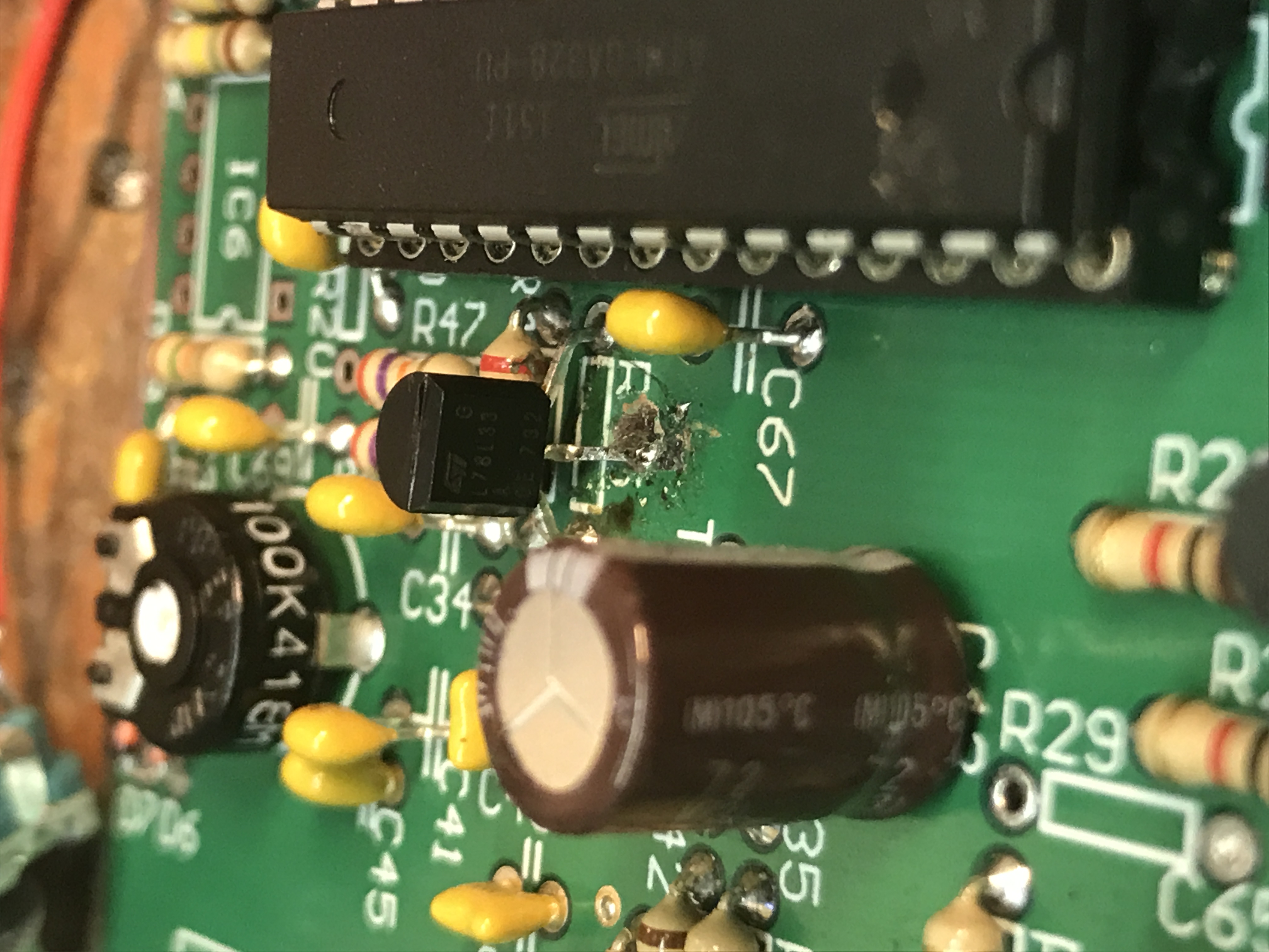
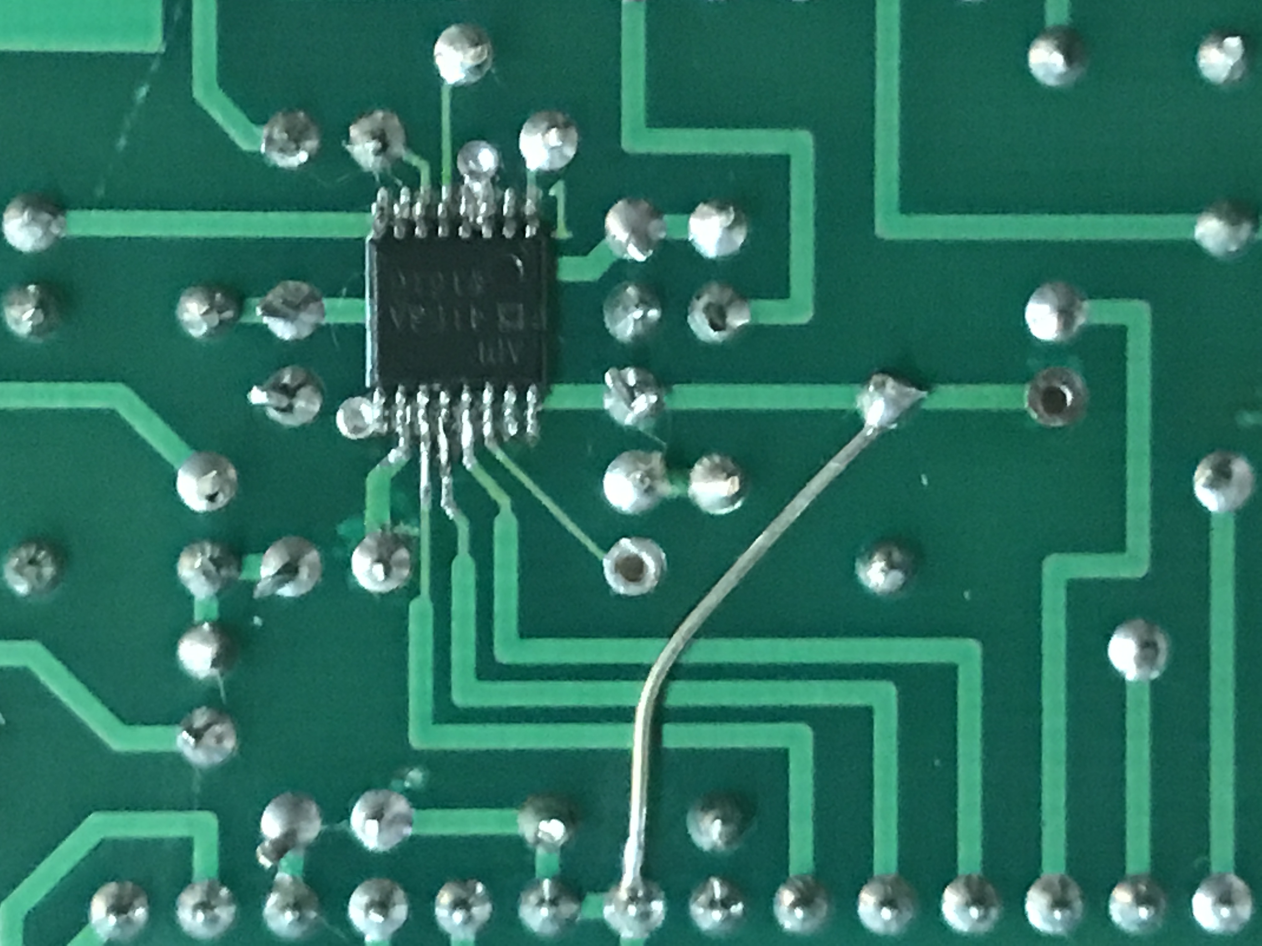
- replace the ADF4113HV with an ADF4153A or -B
- remove R25 and replace it with a 3V3 voltage regulator (L78L33ACZ), with the middle leg soldered to ground
- remove R29 and connect C43/R29 to +5V via a short wire
- update the software in the ATMEGA328 (v4.x)
 |
 |
To increase power I also added a Mitsubishi power module and an external coax relais CX140A. I use the power module M57762 because I had this still in my junkbox and the required input of 0.5-1W perfectly matches the output power of the transceiver. (picture is a version 1 board). However! After some time I discovered that I didn’t receive the repeater in The Hague anymore, at about 60 kms away. It appeared the rx-mar was blown (9V at the output pin in stead of 3,7V). Very likely the lack of a sequence in switching blows the mar. Therefore I upgraded the software in the Atmel with a sequencer: pin PD7 is output to switch the coax relais. This output is active high so switch the relais to ground via a BC547 NPN transistor. When PTT is pushed now first the relais is switched over, and after 200ms the transceiver is switched to TX. When PTT is released, the power is switched back to RX and after a delay of 200 ms the coax relais is switched over. Now everything is workin fine again.
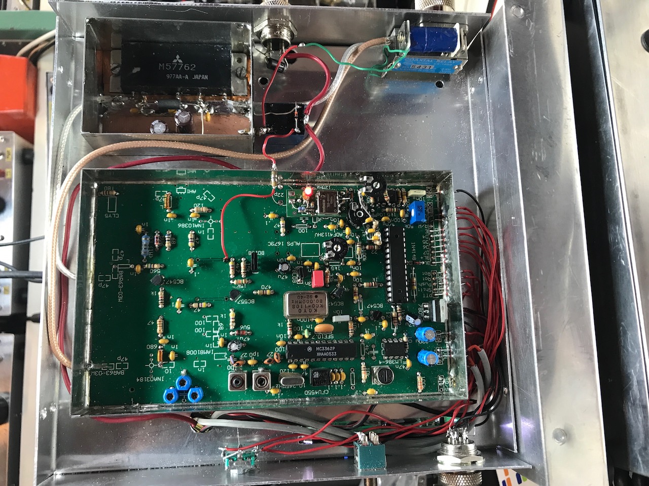
For this additional power amplifier and coax relais the pin-diode switch is removed and the lambda/4 is cut open both at rx and tx side. the RX from the coax relais is now fed directly to C1 and IC1, the RX mar. Due to the higher output and current up to 10A care is needed to improve shielding to avoid any hum. Output is 22W on 1270 MHz, so with a small yagi the advised 100W ERP is easily achievable.
Also the CTCSS is improved. After the lowpass filter to get a sine-hum I added a small trimmer pot to set the level and inject the tone at C35/R24 via a resistor of 15k.