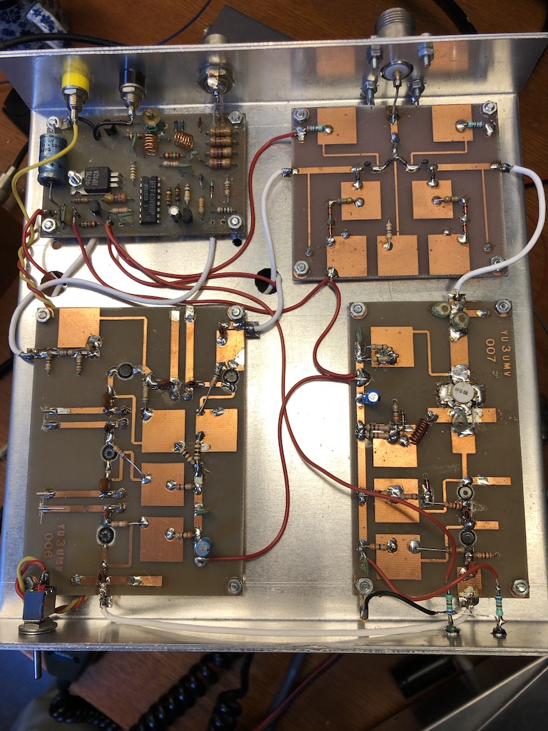
I’ve build my first 23cm transverter after the design of YU3UMV published in UKW Berichte in 1986, see the two following pictures. In the first, you see the tx mixer at the bottom left, the PA giving 1.5W to the right and the pin diode antenna switch. In the upper left the IF and power switching is shown.
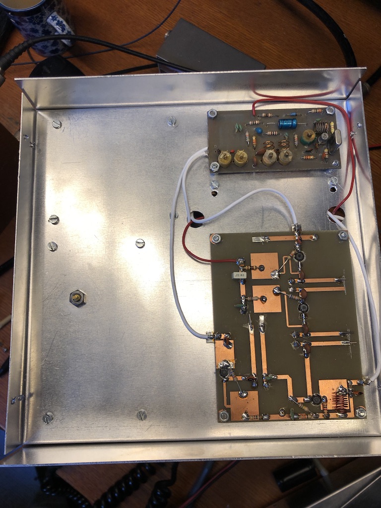
Here you see the underside ot the transverter: the LO giving 576 MHz and the RX mixer. The noise figure wasn’t too good, certainly after modern standards.
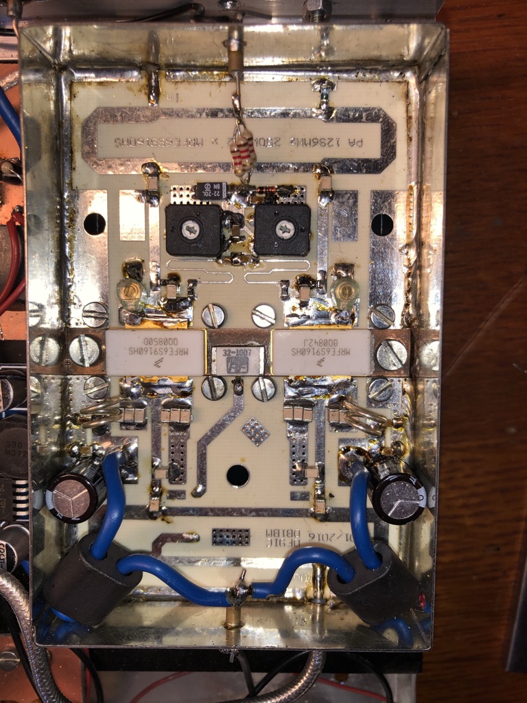
My current 23cm transverter consists of a UEK-3 receive converter and a USM-3 transmit converter. Both are clones and I’ve build them also in the 80’s. The output of the transmit converter is 1W, which is then amplified in a high-power PA designed by DF9IC, using two MRFFE6S9160, good for (in theory) 300W. With 1W drive out of the USM-3 however I reach about 100W out.
The housing is made from 1mm aluminium, 20 cm wide, 20cm deep and 8cm high. It’s a saddle with top and bottom lids.
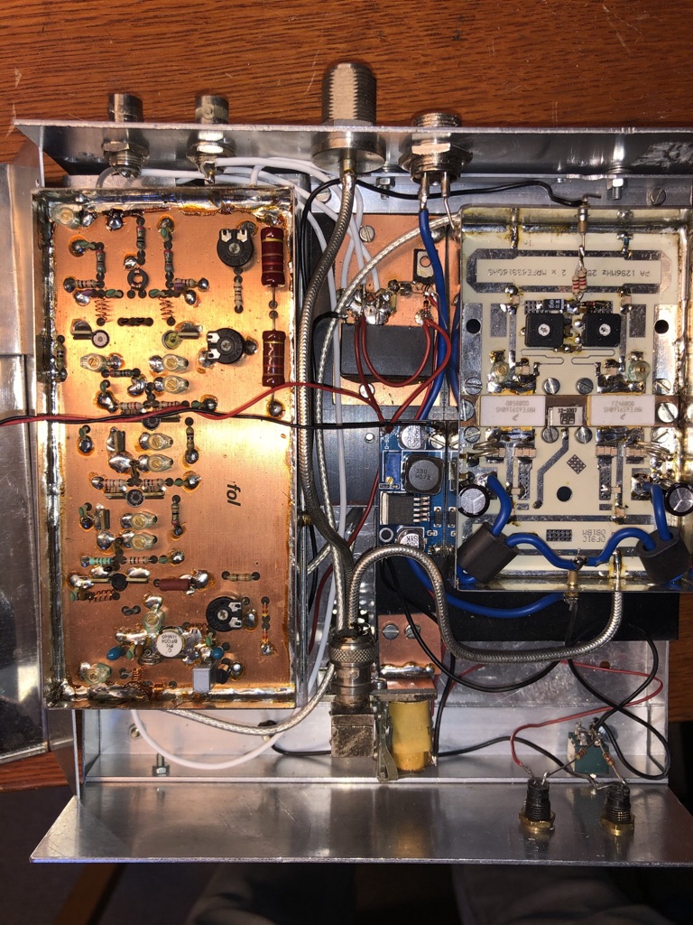
Here you see the USM-3 on the left, and the PA on the right. The transverter is powered with 28V, and for the transverter part this is stepped down to 12V. Also visible is the coax relais for 23cm, and the standard SRS relais switching power and 2m.
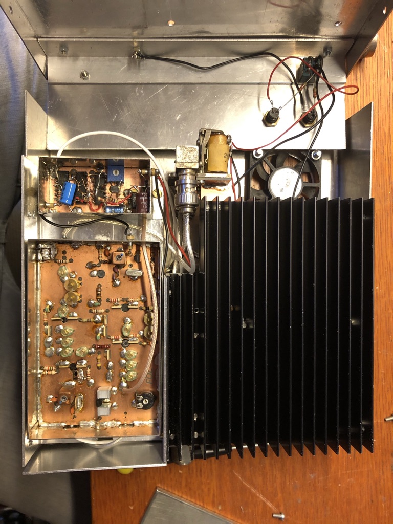
The bottom side contains the RX converter. The 1152 MHz is fed externally to the transmit converter, and also to the 10MHz GPS lock circuit in the top left. Details of the latter can be found elsewhere on this side.
The heatsink is on the bottom, open at at the rear end of the housing. Air is forces from the top via the heatsink out the rear.
The PA in more detail:
