I own a HP Spectrum analyzer with a HP8555A RF-unit. This unit has a direct input which covers DC to 18 GHz. This range is covered in bands, each of which uses a different harmonic of the first LO and up or down mixing to the IF of 2.05 MHz. The internal mixer is used up to band 4+: so roughly from 2×4+2 = 10GHz to 4*4+2 = 18GHz.
For higher bands an external mixer can be used like the HP11517A from HP. The HP88555A is designed to be used up to band 10+, so up to 4.1*10+2.05 = 43.05 GHz. The coaxial cable to external mixer carries three signals: it transports the LO to the mixer (2-4 GHz), it receives the IF back (2 GHz) and it carries a positive mixer bias DC to optimize the mixing in the diode. Do check however if the external mixer is connected internally, in my case it wasn’t:
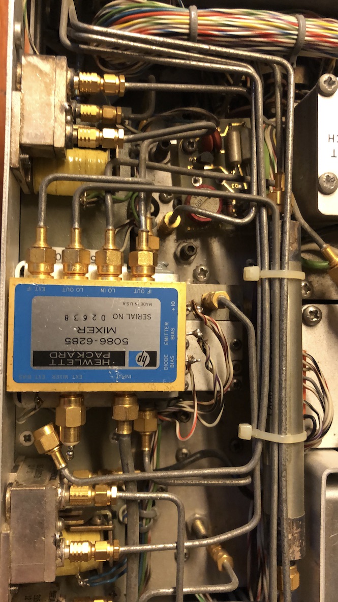
I had to remove the 50ohm dummyload bottom left on the blue mixer and connect external mixer connection to it in stead.
Now it seemed to work but I had no HP external mixer, so I made my own with a piece of WG20 and a BAT15 mixer diode:
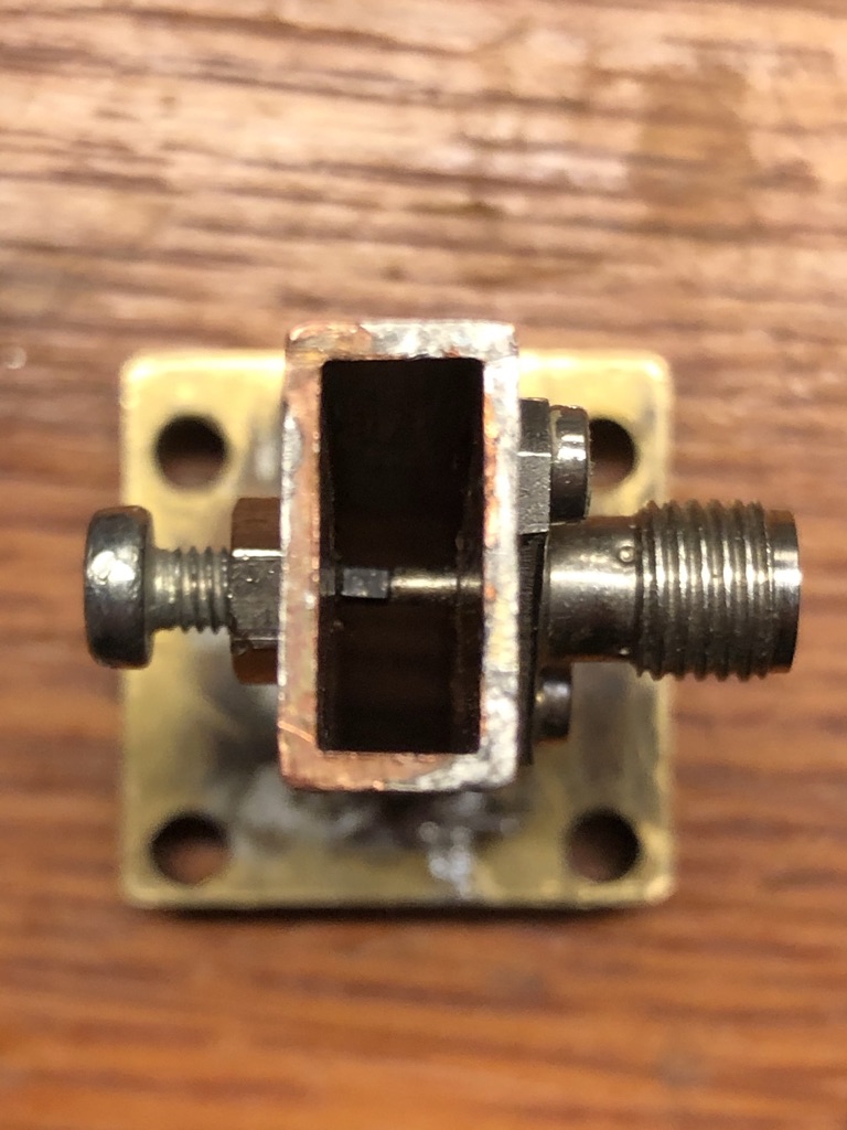
The diode is soldered to an M3 screw and pushed to the inner conductor of the SMA.Indeed a very simple solution, and it works very well. Now 24 GHz amateur band is covered. Although the HP covers the highest band 10+, it also works perfect with higher mixing products. I manually added a band 14+, so now I can measure up to 60GHz: 4.1*14+2.05 = 59,45GHz. The HP is still set at 10+.
Note that both ends of the waveguide are open (still) because it must wideband. Shorting it results in a higher output. I will experiment with aborber foam to give it a proper load.
Take care however of the multiple mixing products since all mixing product show up. HP uses a signal identification trick for this: when the signal corresponds to the selected mode (for example 10+) the signal hops 2 divisions to the left. Any other “hop” corresponds to an other mixing product. When setting the band to 10+ but using for example mixing 14+, the internal processing “thinks” it covers band 10+. The correct signal now hops about 1.4 divisions to the left. The formula for this is
n(true) = (2 div/actual div) * n(set).
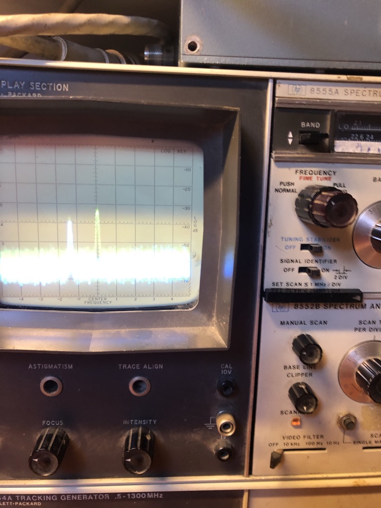
Note that the signal identifier is switched on, and the distance between the peaks is about 1.4 divisions.
I added a scale for the 14+ band:
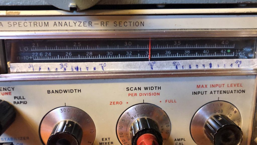
The result is very satisfying. I can now see what I’m doing on 47GHz, and maybe even at 76 or 122GHz (in higher modes).
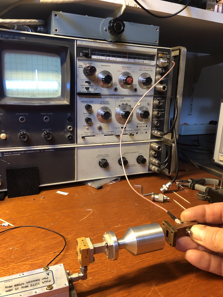
I also have much smaller diodes which will probably work at much higher frequencies: the MA46H120 (thanks Renny PE1ASH). I tried to fix these in the waveguide but did not succeed… pads sized 0.1 by 0.2mm are just too small to mount in the air. So I will make a pcb for this (0.005in) and figure out how to mount this so I can measure up to 122GHz in the upcoming project of VK3CV which I am joining 🙂
